Building the Chesapeake Bay Flattie
Apprentice Level 1 Kit by Midwest Products
Chapter 5: Installing the Cabin
Finally, we are getting to the point of making our little Chesapeake Bay Flattie ship model look like a real boat by adding the cabin.
After removing the cabin sides from die cut sheet #4 and the cabin roof from die cut sheet #6, lightly sand away any burrs or rough spots from the edges.
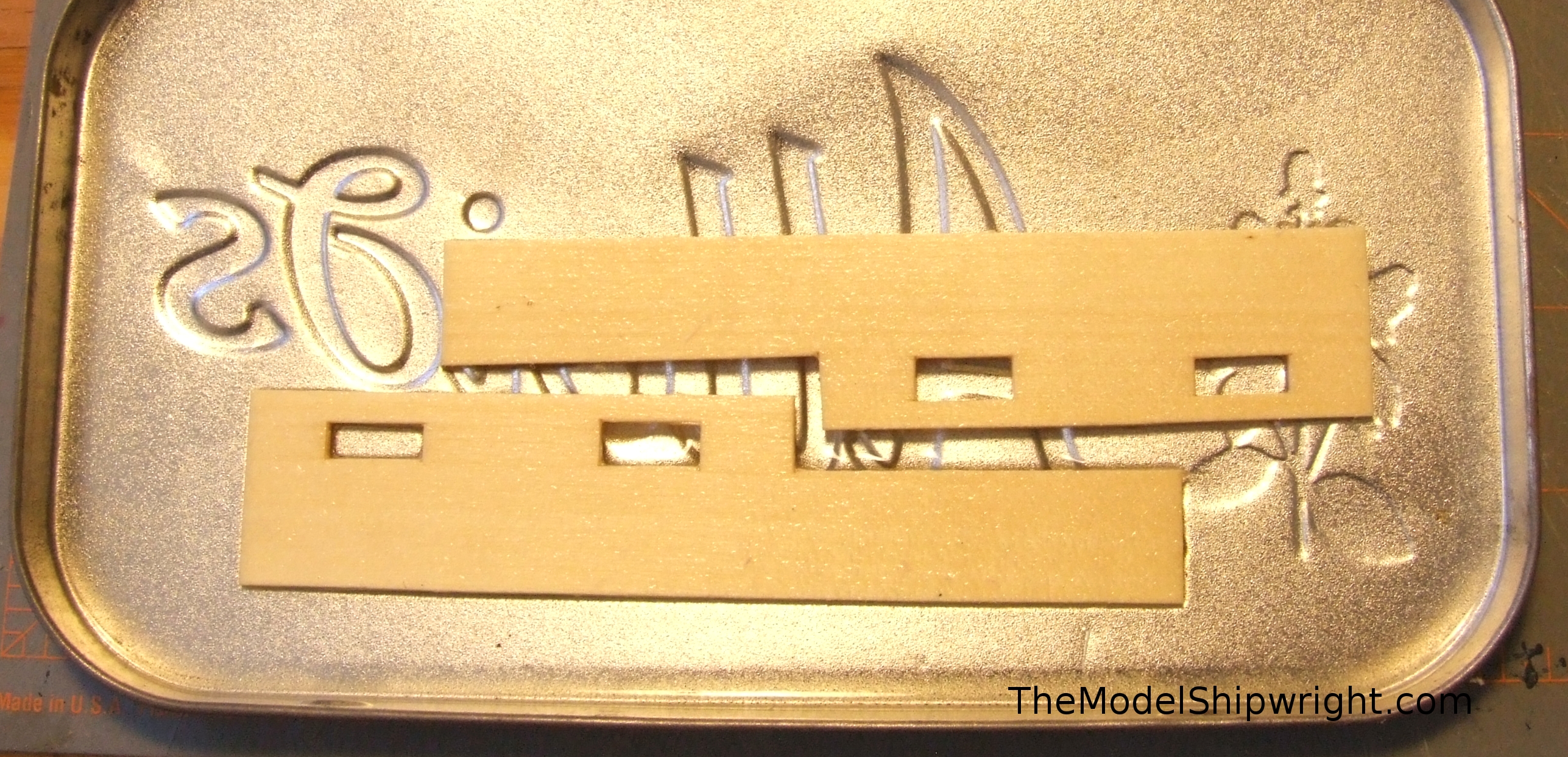
While the cabin sides are flat when removed from the die cut sheet, you can see the edges of the deck that they will mate with are curved. To help impart that curve we first must dampen the wood cabin sides. Water tends to cause the wood to swell, so we are instead using alcohol. Figure 32 shows the cabin sides soaking in a tin of isopropyl alcohol. I use 99% strength to avoid swelling the wood from the water content in the alcohol. Give the parts a good 5 or 10 minute soak to prepare then for bending.
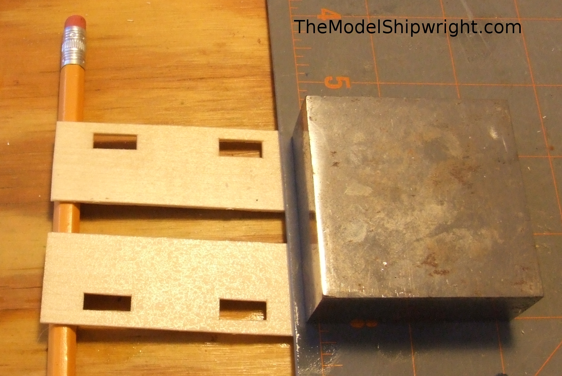
After soaking, we place the rear portions of the cabin sides under the edge of our cutting board and the forward edges on a pencil or similar sized object. Be sure to create a left and right cabin side by laying the pieces as shown in Figure 33 with the edges closest to the windows away from each other. We placed our jeweler’s anvil on top of the cutting board to weigh it down and impart the curve to the cabin sides.
After the cabin sides have dried (another advantage in using alcohol is quicker dry time than water), test fit them to the hull as shown in Figure 34. They may be slightly too long for the opening; if so, using a sanding block, remove enough material from the rear edges of the cabin sides so that they will slide into place snugly between bulkheads F2 and F4. Even after pre-bending, you may need to apply a little pressure to get the cabin sides to perfect contact with the edges of the deck. We used our trusty micro bar clamps for this.
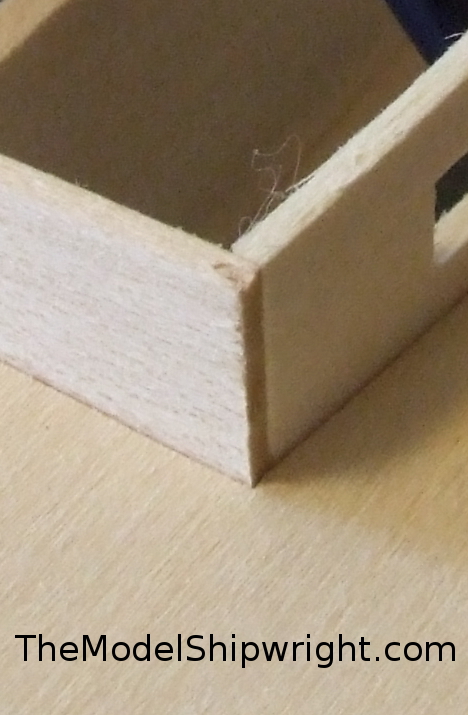
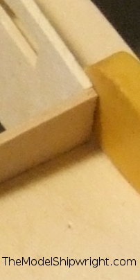
When properly placed, the cabin sides should make contact with the cabin floor, and the top edges flush with the tops of bulkheads F2 and F4 as shown in Figure 34b. Note the cabin sides contact the back edge of F2 and the front edge of F4, but the outside edge of F3.
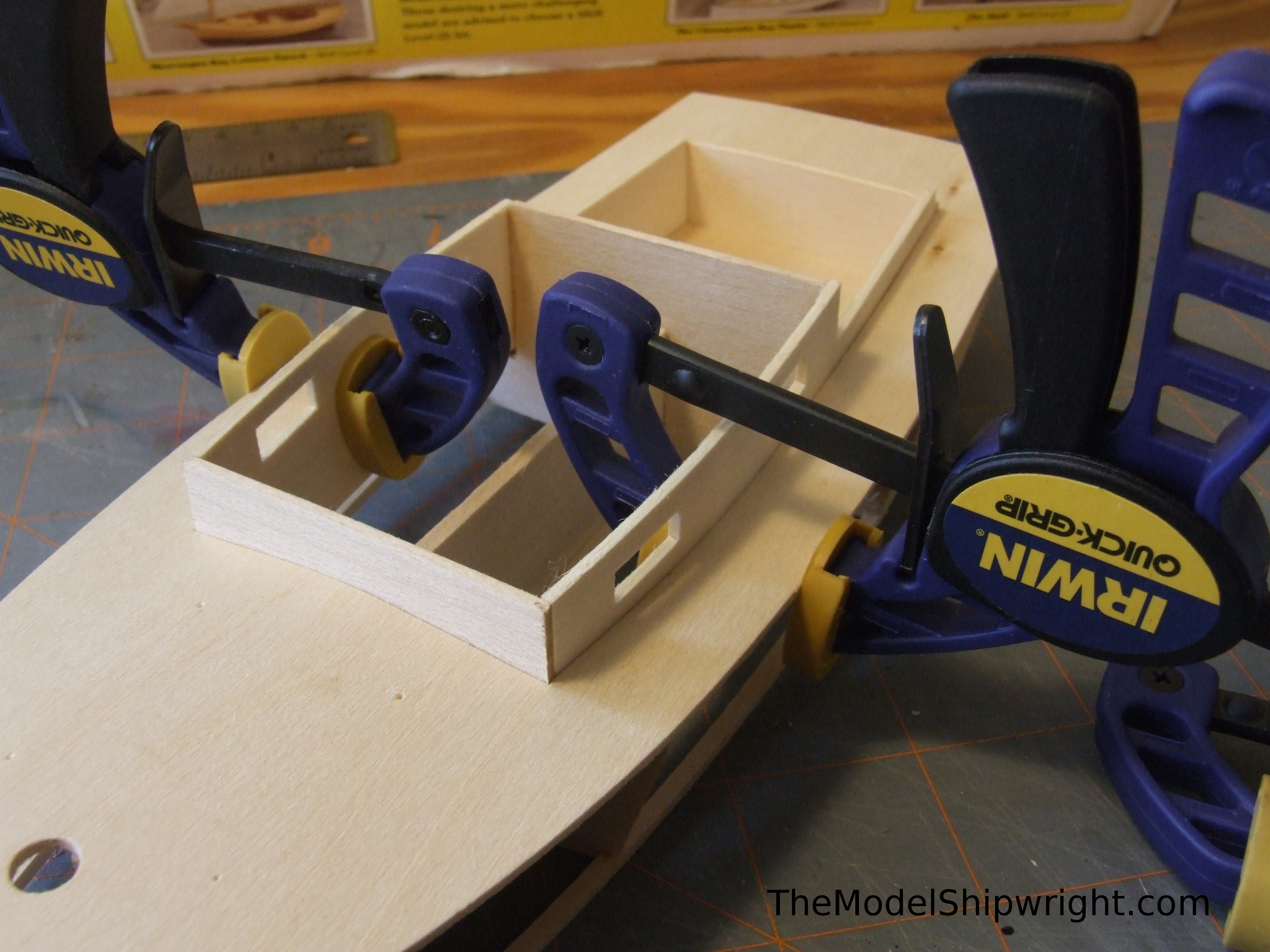
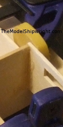
Once we were sure the cabin sides fit correctly, we clamped them in place as shown in Figure 35a. Figure 35b shows the proper placement of the clamp to keep the forward edge of the cabin side in place against F2 and keep it from springing outward. Figure 35c shows the proper placement of the clamp to keep the cabin side in contact with F3. The back edge of the taller part of the cabin side should be flush with the back of F3. These clamp placements are important because they use the strength of the bulkheads to keep the clamps from pushing the cabin sides inward.
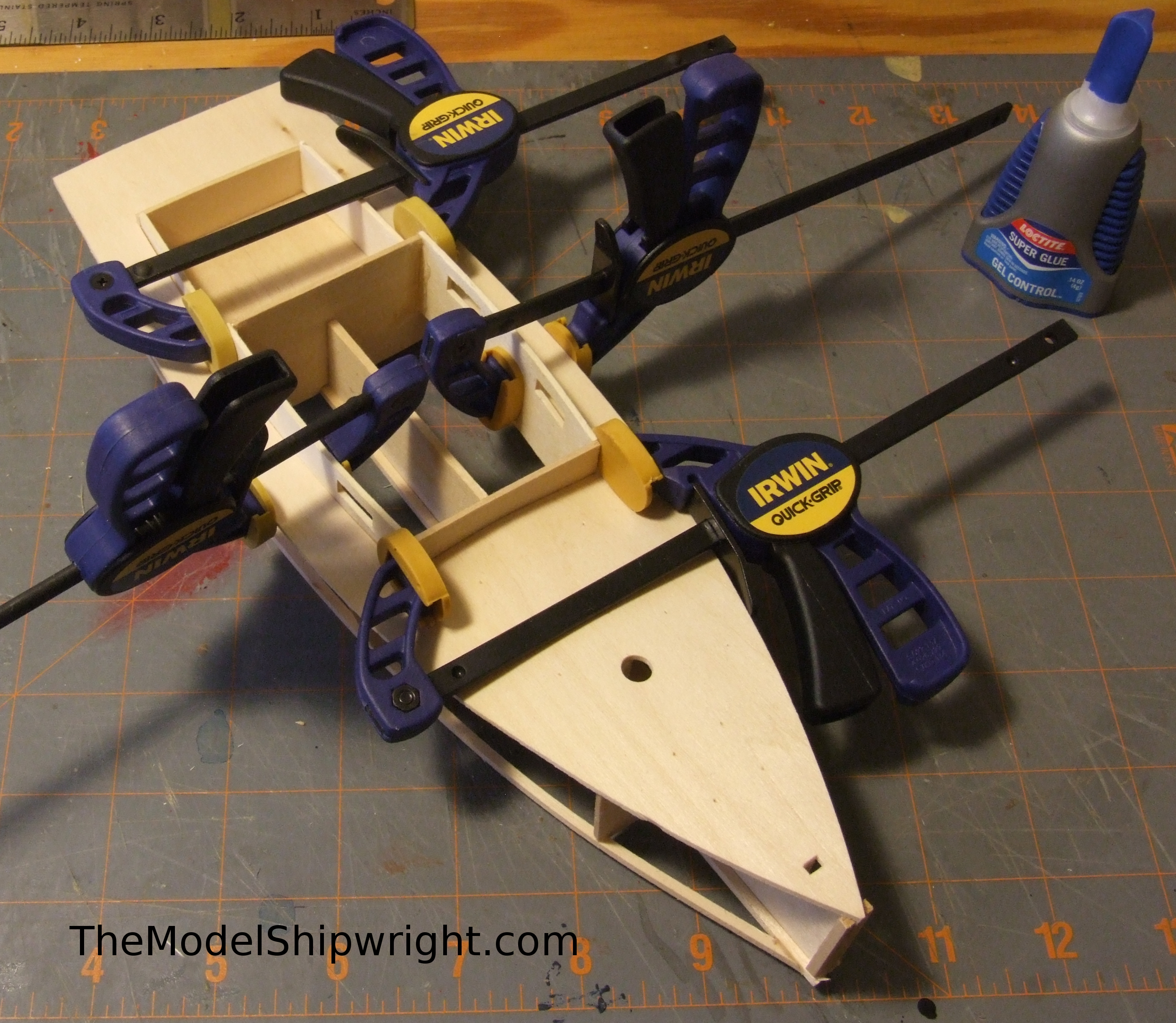
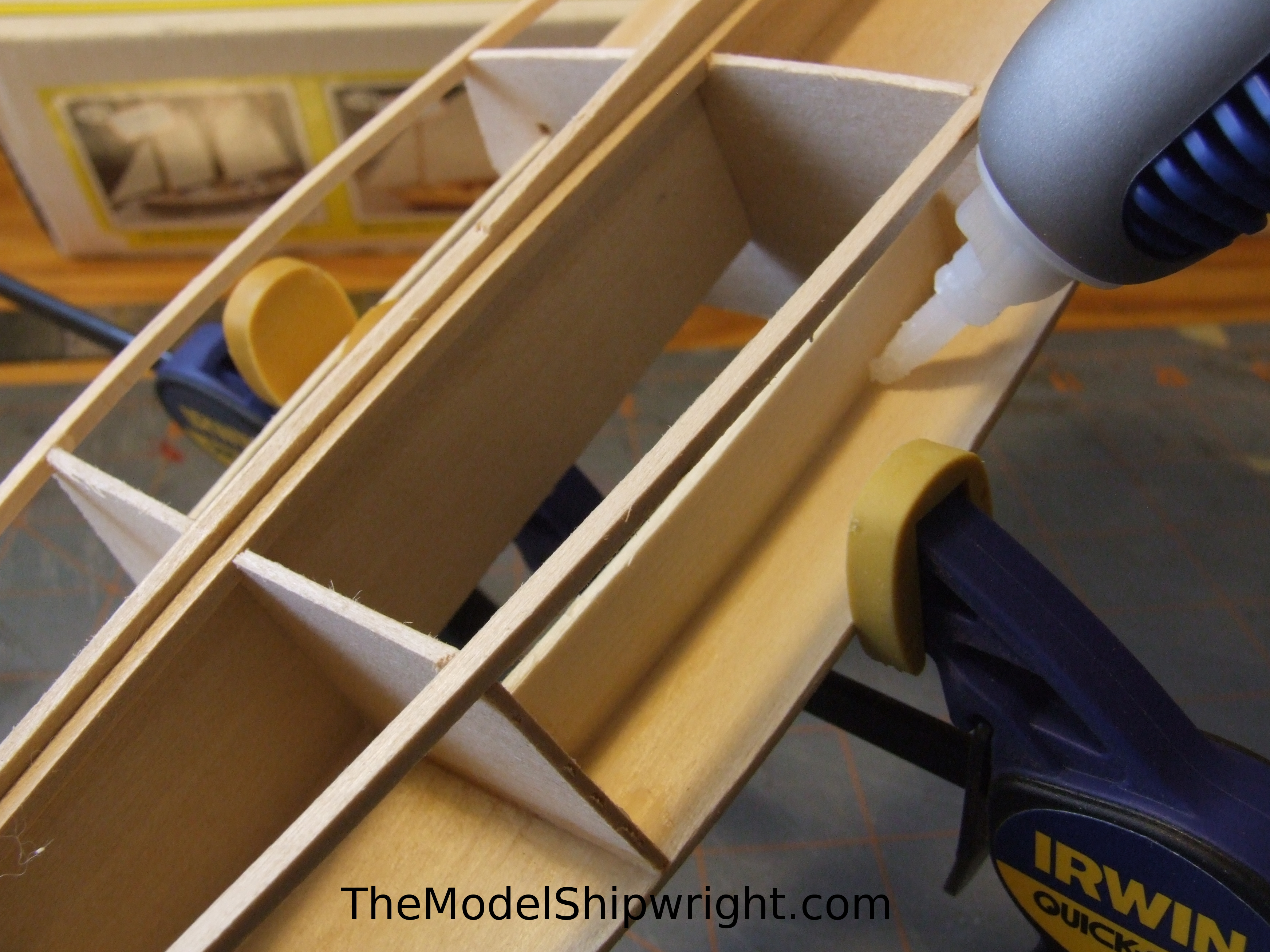
Once the cabin sides are properly clamped, run a bead of CA glue along the joints between the deck and cabin sides, the cockpit floor, and bulkheads F2, F3, and F4. Apply the glue to the bottom side of the deck as shown in Figure 36 and inside edges of the cabin sides where they meet the bulkheads so glue will not show on the outside of the model.
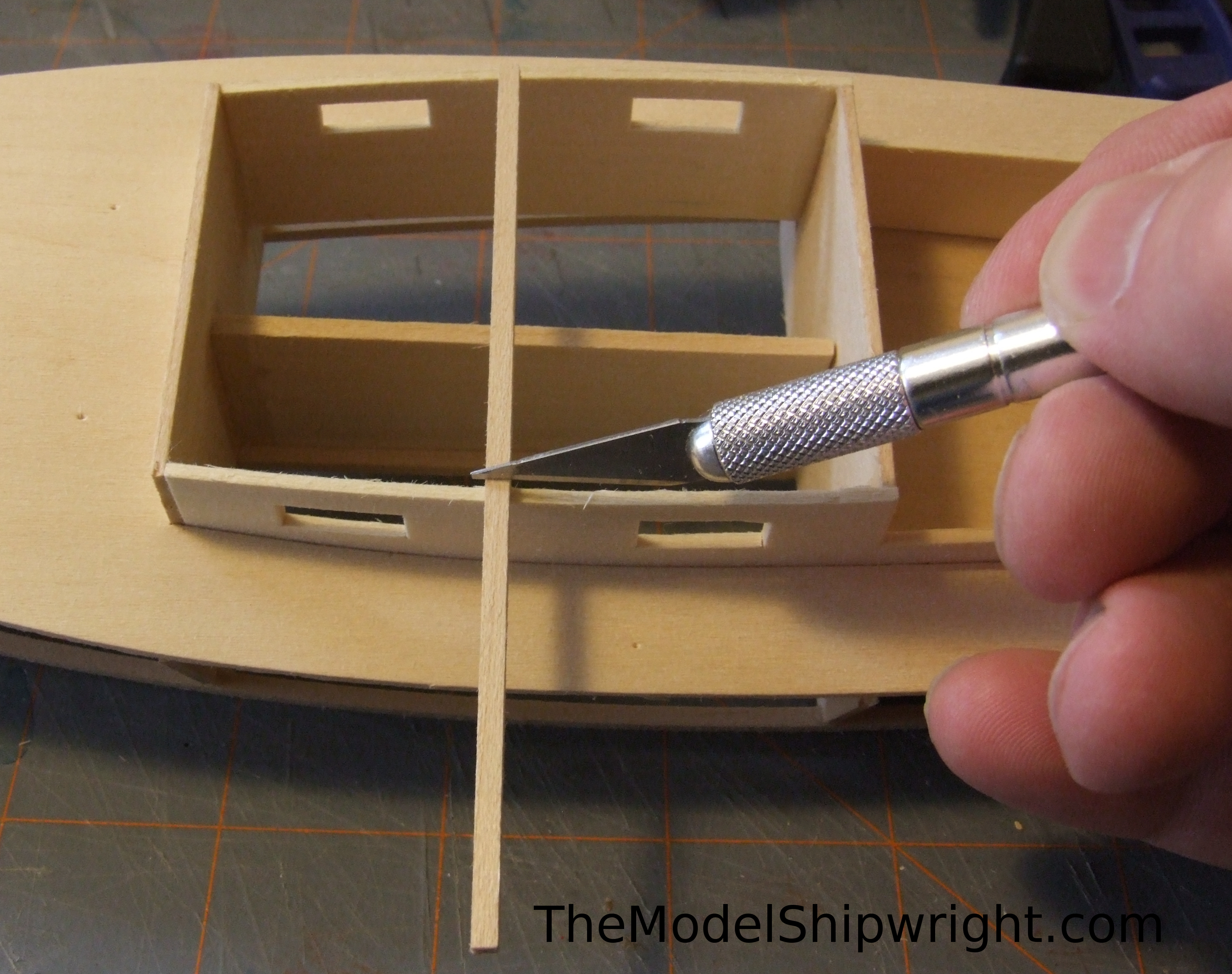
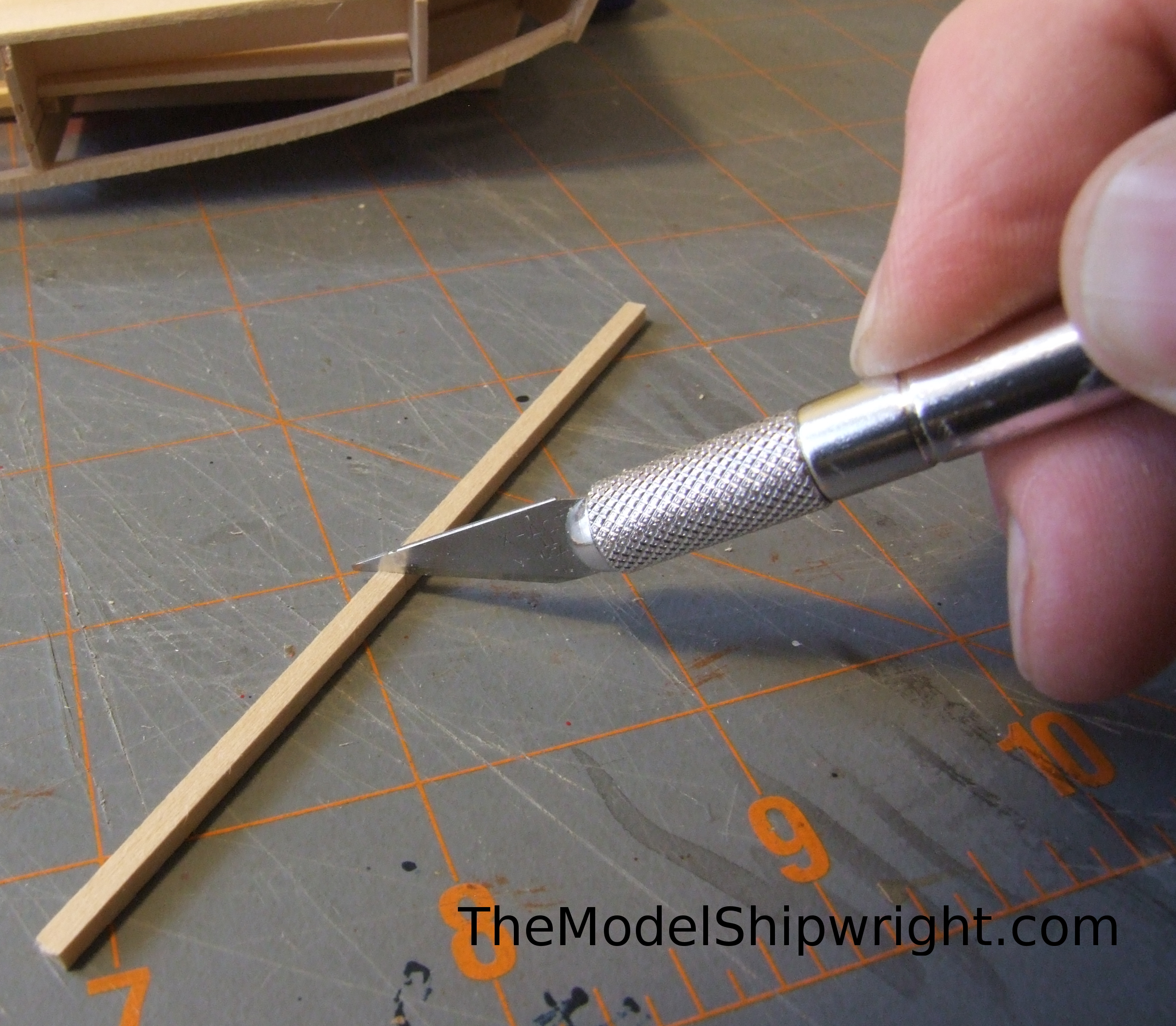
Using a piece of 3/32” square strip, measure the width a cabin roof beam, marking it with your hobby knife as shown in Figure 37. Cut the ends slightly beveled to match the curve of the cabin sides as shown in Figure 38, and glue it flush with the top edge of the cabin sides.
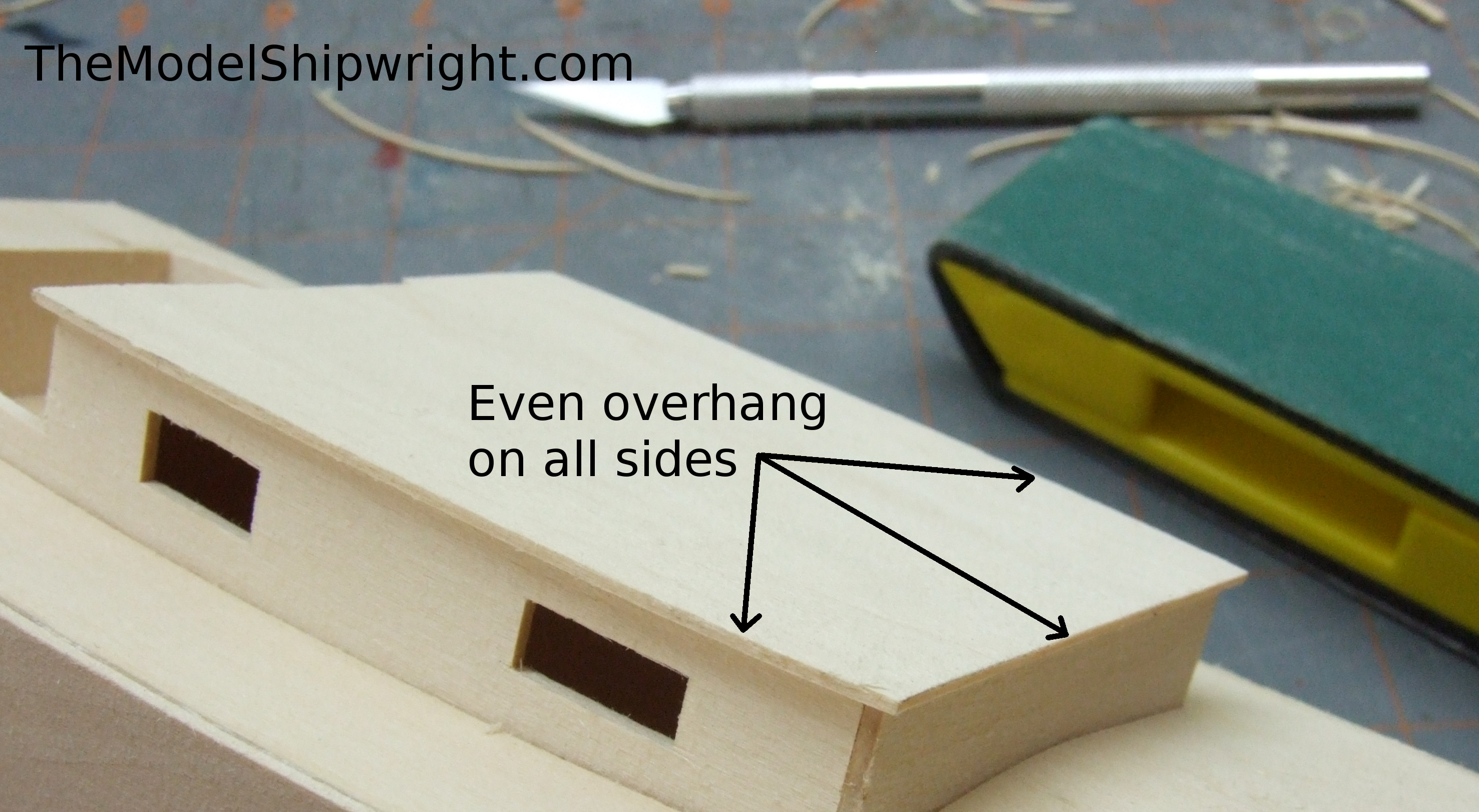
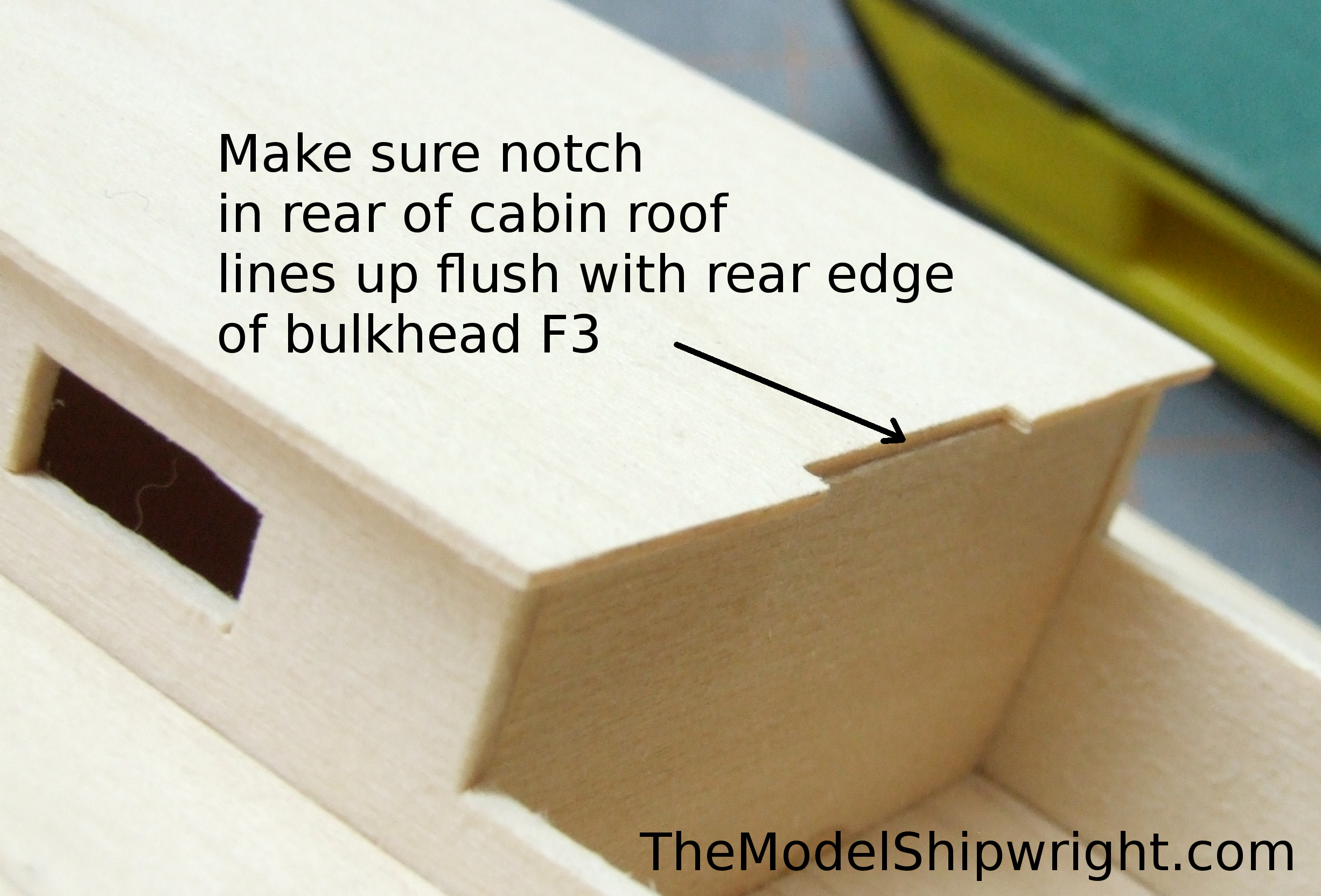
Double check that the top edges of the cabin sides and bulkheads are all flush. If they are not, use a sanding block to match them up. This is important, because if there is even a small difference in height, it will be very apparent after gluing the cabin roof on. This is a very obvious part of the model that you want as perfect as possible. Once you are sure the bulkheads and cabin sides match in height, apply a bead of glue to them and the cabin roof beam. Place the cabin roof onto them, making sure there is an even overhang on all sides, as shown in Figure 39. Also make sure the notch in the rear edge of the cabin roof is flush with the rear edge of bulkhead F4 as shown in Figure 40.
Our little Chesapeake Bay Flattie is now starting to look like a real ship model, instead of just a skeleton!
Up next we will “fair” the hull and add the planking to the sides and bottom of it. This is another procedure that may seem daunting, but isn’t that hard, and is of utmost importance in creating a good-looking model.
Links to chapters
Back to Chesapeake Bay Flattie Introduction
Back to Chapter 1: Assembling the Keel and Bulkheads
Back to Chapter 2: The Deck
Back to Chapter 3: The Mast Step and Bow Stiffeners
Back to Chapter 4: Keel and Chine Strips
Chapter 6: Planking the Hull
Do you have the rest of the directions? It seems to only go through cabin installation.
Thanks for visiting TheModelShipwright.com! We’re working on getting the rest posted as time permits. Next up will be fairing and planking the hull.
We just posted the page showing how to plank the hull: https://www.themodelshipwright.com/construction-articles/building-midwests-chesapeake-bay-flattie-ship-model-kit/building-midwest-products-chesapeake-bay-flattie-chapter-6-planking-the-hull/
[…] Chapter 2: The Deck Chapter 3: The Mast Step and Bow Stiffeners Chapter 4: Keel and Chine Strips Chapter 5: Installing the Cabin Chapter 6: Planking the […]
[…] Chapter 1: Assembling the Keel and Bulkheads Chapter 2: The Deck Chapter 3: The Mast Step and Bow Stiffeners Chapter 4: Keel and Chine Strips Chapter 5: Installing the Cabin […]
Do you have an address where I can send a donation I don’t use credit cards on line
Thank you for the offer, but we don’t accept checks or money orders at this time. You can support us just by spreading the word about our site!
[…] Chapter 1: Assembling the Keel and BulkheadsChapter 2: The DeckChapter 3: The Mast Step and Bow StiffenersChapter 4: Keel and Chine StripsChapter 5: Installing the Cabin […]