Chesapeake Bay Skipjack E.C.Collier is a great choice for
Scratch-Building a Plank-on_Bulkhead Ship Model
Easy curves and flat sides make planking easy
One of the most popular methods of scratch-building ship models is the plank-on-bulkhead method. In this method a number of bulkheads are used to build a skeleton of the ship (see Figure A, the bulkheads for Midwest Products Chesapeake Bay Flattie of which we are chronicling the building of here), which is then covered with planking.
The shape of the ship’s hull will determine how many bulkheads the model builder must make to get the shape of the model correct. The more curvy the hull, the more bulkheads will be needed to make sure the planks hold the right shape.
For this project, we chose the Chesapeake Bay Skipjack E.C. Collier, shown in Figure 1. One of the oldest remaining historic oyster dredgers, the Collier now resides at the Chesapeake Bay Maritime Museum. The easy curves and flat sides of this ship make planking easy – an ideal first project for the scratch-builder who wants to move from solid-hull models to the plank-on-bulkhead method.
The shape of the bulkheads is determined from the section – or body – plan for the ship. As a refresher to our article How to Read a Ship Plan, the section plan shows the shape of the hull as if it were cut like a loaf of bread. Each section line delineates the shape of the hull at a specific point, which is marked on the half-breadth and sheer plans, as shown in Figure 2.
The lines plan for the E.C. Collier, shown in Figure 3, is marked off into 10 sections from bow to stern, which is enough to create the broad curves of a Skipjack. The section plan only shows half the section from the centerline out to the sheer because the ship is symmetrical, so there is no need to show both sides. The left side of the section plan shows the sections from mid-ship aft to the transom, while the right side shows from mid-ship forward to the bow.
You will notice that both the sheer plan and the section plan are drawn from a baseline marked on the plan. The sections are at 90 degrees to the baseline on the half-breadth plan. The baseline for the section plan is at 90 degrees from the ship’s center-line, so these two lines give us a point from which to measure to ensure the hull we build is square and true.
However, the easiest way to build a plank-on-bulkhead model is to fasten the bulkheads upside down to a building board to hold them square until enough of the other framework is added to hold them in the proper alignment. The problem that presents itself, then, is that the sheer is not flat, but sweeps upward from admidship to the bow and stern. So, we must determine the height each of the bulkheads must mounted above the building board to align them correctly.
Since the baseline is the same for both the sheer and section plans, our first task is to move the section plan so the baseline under it matches the position of baseline under the sheer plan, as shown in Figure 4.
Once this is done, we draw a new baseline, parallel to the other one, above the sheer just touching the highest point of it. This line represents the surface of our building board, and is extended from the sheer plan over the section plan, showing how far each bulkhead must be mounted above the building table to maintain proper alignment with the others.
Then, as shown in Figure 5, we draw vertical lines from the point each section line meets the sheer to the new baseline, the surface of our building table. This will create “legs” to hold each bulkhead at the proper height.
Since the section plan only shows the shape of one half of each of our bulkheads, we need to copy it to create the other half. This can be done with tracing paper, but with the advent of PhotoShop and other image-processing software, this task is made much easier. I use a share-ware version called Graphic Image Manipulating Program (GIMP) which is available for free here. However, if you are not familiar with this type of program, a commercial version that comes with a training tutorial and user’s manual may be a better choice. The learning curve can be quite steep if you’ve never used image manipulation software before.
First, before anything else, make sure you have two copies of the section plan. Using the rectangle select tool, available in the image manipulation software, select the section plan including both the original baseline and the new one you drew above it, then copy it (from the “Edit” menu choose “Copy”) and paste it (From the “Edit” menu choose “Paste”) onto the plan. You can move this pasted layer using the mouse by clicking and dragging it, or with the arrow keys. Once you have it moved to another spot away from the original, move the cursor off of the new layer. In most programs, the cursor will change to an anchor icon. If you click the mouse, this will anchor the new layer to the original one.
The next step, as shown in Figure 6, is to use the “Lasso” tool, to carefully select the side of the section plan we want to duplicate and copy it to the clipboard (from the “Edit” menu, choose “Copy”). Then paste it back onto the image (from the “Edit” menu, choose “Paste”). The image still must be flipped and aligned to the other side.
From the “Layer” menu, choose “Transform” then from the sub-menu that opens, choose “Flip Horizontally.” You can then use the arrow keys or the mouse to move the flipped layer into alignment with the original side of the section plan, as shown in Figure 7. Move the cursor off the layer so that it changes to the anchor icon, and click to anchor the layer in place. The steps for Figures 6 and 7 must be repeated with the other copy of the section plan, using the other side of it, to create all the bulkheads we need.
Now that we have the section plan at the full width we need, we need to create the bulkheads from it. I copy and paste this full-width section plan as many times as there are section lines on it. Then, as shown in Figure 8, on each one of the copies, eliminate all but one of the section lines, a different one on each copy. I also copied the deck camber (the curvature of the deck that helps water to flow off) from a cross section on the plan and pasted it on from one sheer to the other. The camber of the deck is an arc of a circle, so it can be used on each bulkhead just by lining up the center-line and cutting off any excess that extends past the sheer line.
Figure 9 shows all of the bulkheads created through this method from both copies of the section plan. But, we aren’t quite done yet. As shown in Figure 10, below, additional vertical lines are drawn to show the width of the “legs” on each bulkhead, and, if you are building a big enough model, draw lines to cut out the middle of the bulkhead to save weight or make room for radio-control gear.
Up to this point, for simplicity’s sake, the plan has been shown with the bulkheads keel-down. But, since we are building it upside down, now we flip the image over so it shows more clearly it’s actual position on the building board, as shown in Figure 11, below.
We need to mark where we will cut out spots for the longitudinal frame members that will hold the frames in place before planking is added. These pieces are:
The keel, which runs along the very bottom of the ship (top in this illustration). The keel is the backbone of the ship, and must be sturdy to keep the vessel from “hogging,”where the ends – that are less buoyant than the middle of the ship – sag downward. Our model will be about 48” long, so our keel will be 3/4” by 3/8”. When cutting the keel slots into the bulkhead, remember that it needs to sit high enough to touch the point where the two bottom lines meet along the center-line. This means that when you put it in place, the edges of keel will be slightly above the edge of the cut-in. This is correct, as the keel will be shaped later to match the angle of the bottom of the bulkheads.
The chine logs, which run along the corner where the side of the ship meets the bottom. Ours are 1/2” square, and, like the keel, must be set in place to reach out to where the lines of the hull sides and bottoms meet. As with the keel, the edges of he chine logs will be slightly higher than the depth of the slot you cut to fit them in.
The sheer clamps run along the sheer (where the side of the hull meets the deck). Ours are 3/4” by ¼”. The sheer clamps are cut into the bulkhead so they fit flush with the edge of the bulkhead at at the same angle.
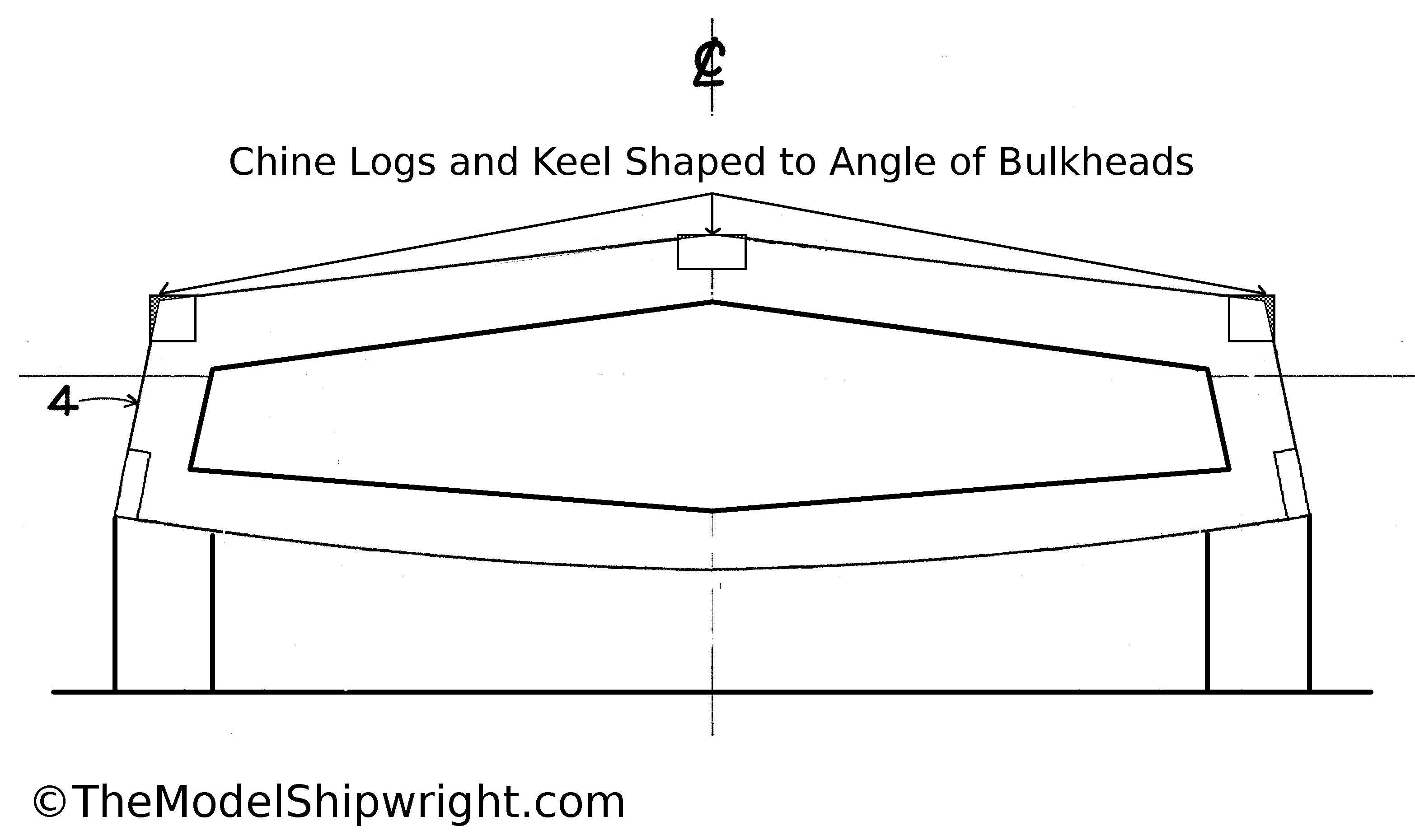
Figure 12 shows where the keel and chine logs will be shaped later in assembly, with the shaded portions removed, to clarify the instructions in the previous figure.
Once we complete this process with all of the bulkheads, we will begin cutting them out on Page 2 of Scratch-building a Plank-on-Bulkhead Ship Model.
1. Skipjack E.C. Collier sail plan delineated by Holly A. Olden and Laura E. Salarano in 1989 for the Historic American Engineering Record
2. Skipjack E.C. Collier lines plan delineated by Stephen D. Koopman, Holly A. Olden, and Laura E. Salarano in 1989 for the Historic American Engineering Record

[…] Chesapeake Bay Skipjack E.C. Collier […]
Hi I am trying to log in, have been on site before, but can not log in, also how do i get or purchase the E.C. Collier skip jack plans THANK YOU DON FARR
If you click on the plan image on the webpage, it will open the full size image file. Right-click on that image, choose “save image as” and choose where you want to download it to.
CAN ANYONE HELP ME HERE. THANK YOU Don Farr
[…] Chesapeake Bay Skipjack E.C. Collier […]
[…] models), Building a Bread-and-Butter Solid Hull Ship Model (a better method for larger models), and Scratch-Building a Plank-on-Bulkhead Ship Model (which gives a more prototypical experience of planking the […]
[…] a Bread-and-Butter Solid Hull Ship Model (a better method for larger models), and Scratch-Building a Plank-on-Bulkhead Ship Model (which gives a more prototypical experience of planking the […]
[…] subject of our article on plank-on-bulkhead construction, the E.C. Collier is one of the last of Maryland’s sail-powered oyster dredging fleet. As […]
That’s really nice post. I appreciate your skills. Thanks for sharing.
Thank you for visiting the website and your kind words!
This looks like a perfect design for a 1st ship. thank you very much for posting the information. Hope I have a good 1st go at it.
Thanks, and good luck!
Hey good day sir I’m planning on building model ship but the only material i have is a sintra board or styrene is it good alternative for wood?
I’ve never tried it, but I’ve seen several people online who use styrene for model ship building.
I would like to build this model also but at the end under Figure 12 it says the next step is to cut out the bulkheads starts on Page 2 ?? I can’t find page 2. Can you help please ??