Building the Chesapeake Bay Flattie
Apprentice Level 1 Kit by Midwest Products
Chapter 3: The Mast Step and Bow Stiffeners
Mast Step
Next on our Midwest Products Chesapeake Bay Flattie model ship kit is placing the mast step that supports the boat’s mast.
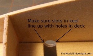
Before proceeding, take a look at where the mast slot in the keel meets the mast hole in the deck, shown in figure 14. Make sure the edges of the mast slot line up with the mast hole. If they don’t, trim the edges of the slot that overhang the edge of the mast hole. Then, check the fit of the 1/4” x 12 2/3” dowel that will be used to make the mast in the mast hole and mast slot.
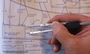
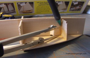
Once you are sure the mast slot and mast hole are lined up, and the mast dowel fits, measure the distance of the mast steps from the deck at F2 on the plan, as shown in Figure 15. I used a pair of dividers, then, being careful not to change the width of the dividers, place them on the keel at the joint with F2. Mark the distance indicated by the dividers as in Figure 16.
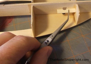
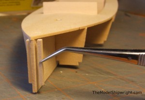
Remove the two mast steps from the die-cut sheet, and using tweezers, test the fit as shown in Figure 17. Make sure the half-circle hole in the mast step lines up with the mast slot in the keel, and the mast step fits tightly against the keel and bulkhead F2. Use a sanding block if needed to adjust the fit.
Once you are satisfied with the fit, apply a bead of glue on the edge of the mast step, and attach it to the keel and bulkhead F2.
Bow Stiffeners
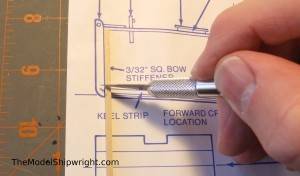
Next, using the remainder of the piece of 3/32” square basswood used to cut the braces on bulkheads F2, F3, and F4, cut two bow stiffeners to the length shown on the side view of plan #1. An easy way to do this is shown in Figure 18: place the wood directly over the plan and marking it with your utility knife blade. Then cut through the wood at that mark on your cutting mat, away from the plan to avoid damaging the plan.
Glue a bow stiffener to the keel on either side, even with the front edge of the keel, as shown in Figure 19.
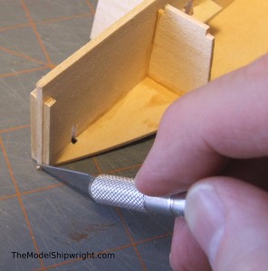
Then, trim the front of the deck even with the front edge of the keel, as shown in figure 20.
Back to Chesapeake Bay Flattie Introduction
Back to Chapter 1: Assembling the Keel and Bulkheads
Back to Chapter 2: The Deck
Chapter 4: Keel and Chine Strips
Chapter 5: Installing the Cabin
Chapter 6: Planking the Hull
[…] 1: Assembling the Keel and BulkheadsChapter 2: The DeckChapter 3: The Mast Step and Bow StiffenersChapter 4: Keel and Chine StripsChapter 5: Installing the […]